(Click for full-size picture)
|
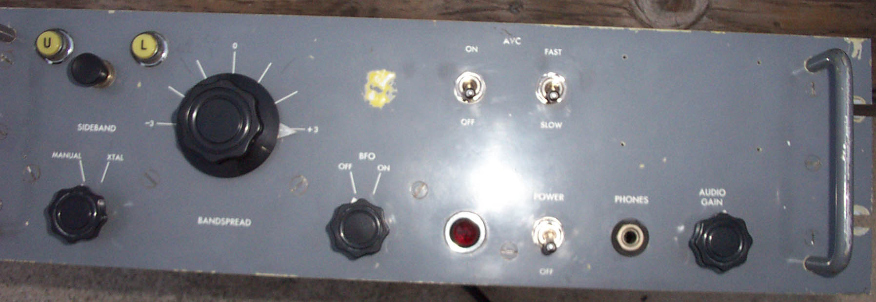
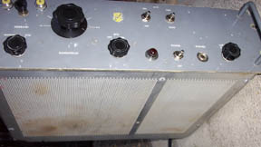
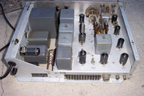
This is a Technical Materials, Inc CV-591A/URR, serial number 2836 (I think) SSB adaptor. It takes
the IF output from any number of receivers, such as the Collins R-390, R-392 or R-390A, or the
Hammarlund SP-600. It has no field changes, so it can be used with its remote-control interface,
which connects in the back. This is also known
as the TMC MSR-4.
This unit was in relatively good shape - a tribute to how well-made these devices were. This one
is a bit unusual in that it has both the top and bottom covers. I did not do much on the cosmetics
except to clean it up carefully. I did go through the electrics of the entire unit in some
detail, replacing any parts that were leaky or out-of-spec. I also replaced all the tube
shields with the black IERC type. The front ID panel with the serial number on it was missing.
There is a hand-written note on the back that identifies what may be the serial number, so that
is the number I am using. There is one circular scratched zone on the front panel maybe 3/4" wide.
It is yellow, which is the color of the zinc-based primer that was often used for aluminum
panels. Some bare metal shows through.
The bat-handle switches on the front panel were falling apart. I replaced them with high-quality
(and expensive!) modern Carling switches.
This unit works well and sounds great.
If you have not heard the performance of these units, it is quite remarkable how clean
the SSB is. It sounds a lot like AM. The CV-591 has several additional filters to knock
out nearby interference. These are all LC filters - no crystal filtering in this unit. It can
also be used on AM to select just the upper sideband or lower sideband separately, in case
there is interference on one and not the other.
|
(Click for full-size picture)
|
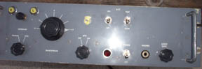
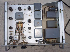
This shows the underside of the power supply. I removed the old (leaky) electrolytic capacitors
and replaced them with under-the-chassis modern high-ripple long-life alluminum electrolytics of
considerably higher capacitance. I can detect no 60 Hz ripple anywhere. I did replace the fuse holder,
however, which was falling apart. I left the 5Y3 rectifier tube (rather than replace with
solid-state) since there is nothing particularly wrong with this arrangement. I did replace
the tube with one that tests better. I also connected a modern 3-wire power cord and grounded
the chassis to the mains ground.
The 4.5K dropping resistor on the 0A2 regulator was open, so I replaced it with a modern
10W film resistor. I strapped it with panduits to the original mounting shaft,
right where the old one was. It does get pretty warm.
|
(Click for full-size picture)

|
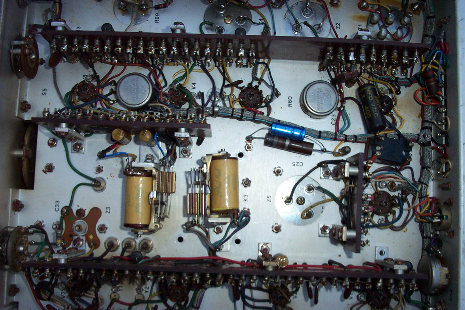
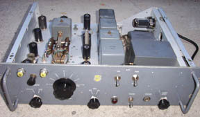
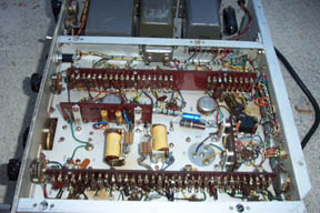
This is just to show you how well-built these units are. Every part is securely held down
on these component carrier strips. Note the L-brackets that hold the component carriers - those
parts aren't going anywhere! Very few of the capacitors showed any significant leakage, so I
did not have a lot to do here. The relays and the relay contacts were in perfect working order.
I did have to replace one capacitor (the pretty blue one in the middle) that was the cathode
bypass for the 6AQ5 audio output stage. There were several wires that were either broken or
looking like they were going to break. I replaced them, or at least covered them with shrink
tubing for mechanical reinforcement. I checked many (not all) of the resistor values and they
all seemed well in spec.
|
(Click for full-size picture)
|
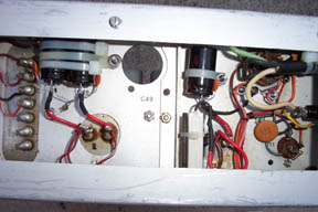
This shows the black IERC tube shields. When I got this unit, it was missing the sheet-metal
cover for the stepping relay. I didn't have a replacement for it. Sorry. I did clean the contacts
of the stepper, and it works quite well. Like all these units, it makes quite a racket when
you switch between upper and lower sidebands, but I suppose that is part of its vintage charm.
|
(Click for full-size picture)
|
I tested all the tubes and replaced any weak or dead ones with no substitutions in the
tube types (none is necessary that I know of). This includes the 6J6 reactance modulator
for the remote-control. This allows you to tune the device remotely
using a control voltage of -4.5 to +4.5.
|
(Click for full-size picture)

|
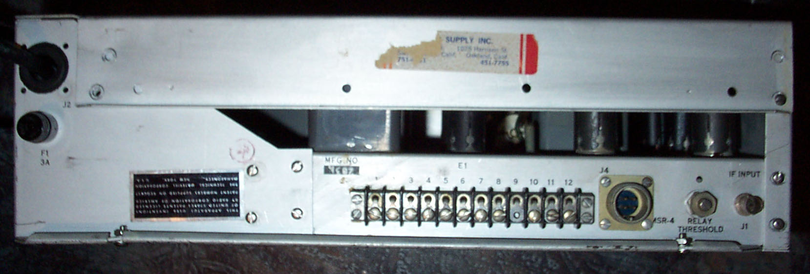
This just shows the rear panel of the unit. The round connector is for audio out, although
the audio out also shows up on the terminal strip, at multiple values of impedance. The
rear terminal strip also has the remote-control connections: bfo relay, sideband change,
and manual tuning. It does not seem to be possible to change the crystal/manual setting
remotely.
You can see (upside-down) the small, hand-written number that I am
taking as the serial number of the unit.
|