(Click for full-size picture)
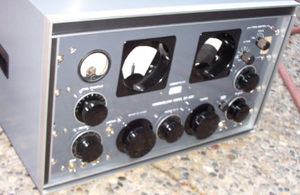
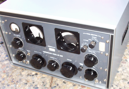
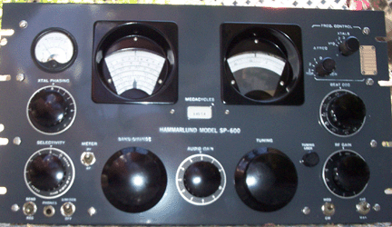
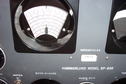
I did refinish the front panel. I used a darker grey so the engraving and the dials stand out better. I did repaint the knobs on this one. They were quite dull. I did not try to repaint the meter. I was worried that some paint would get into the mechanism. I did put dial overlays on the frequency read-out, the vernier, and the band-change indicator (the originals are still there - I just turned them over and put the dial overlay on the "back" side). I made my own dial overlays from a more recent receiver.
This receiver is unusual in that it has a steel front panel, rather than the standard aluminum. This adds maybe 10 pounds to the overall weight, but you don't have to worry about weapons discharge in your shack blowing a hole in this panel(!).
(Click for full-size picture)

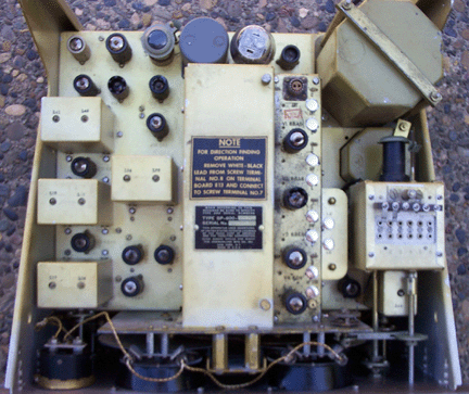
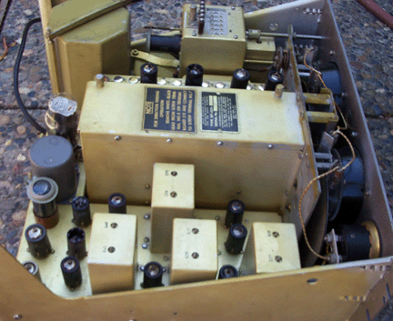
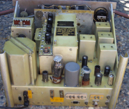
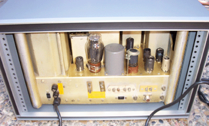
De-Oxit was applied to all the tube sockets. The chassis did not need any work - it was clean and square. It was apparent that this receiver had not been dropped or otherwise mishandled. There were no bent edges or crushed corners. I replaced the missing tube hold-down clips on V3, and V17.
(Click for full-size picture)
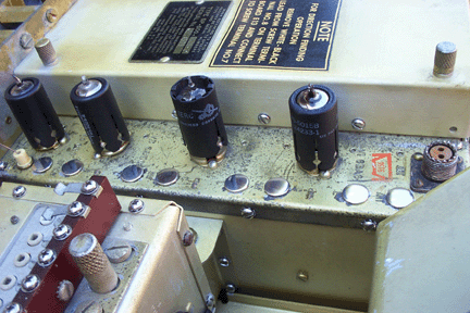
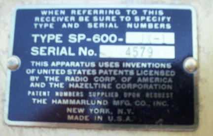
Note the text above the serial number plate. This reiterates the procedure (noted above in discussing E13, behind the power supply) for converting for DF (Direction Finder) use. You move one wire from one screw terminal on E13 to the next.
(Click for full-size picture)
(Click for full-size picture)
(Click for full-size picture)
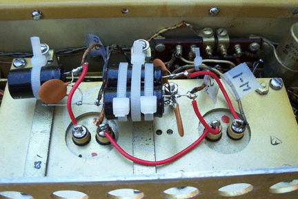
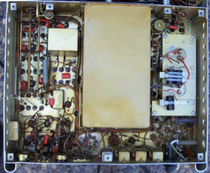
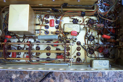
This also shows the rectangular E13 terminal block (behind the power assembly). The two brass screws on the top are so that you can change the gain of the first two TRF stages from "Normal" to "DF" ("Direction Finding"). Doing that effectively disables the AVC on the TRF stages, running them at maximum gain all the time. In our modern world with 50KW broadcast transmitters on every hilltop, I would advise you to leave it on "normal." Note that this receiver has a different AVC structure from most others - the AVC voltage is supplied to V6 (6BE6 second mixer) and V7 (6BA6 gate) as well as the TRF and the IF stages.
(Click for full-size picture)
