The TMC R-5007 (AN/FRR-49(V)) Page
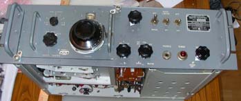
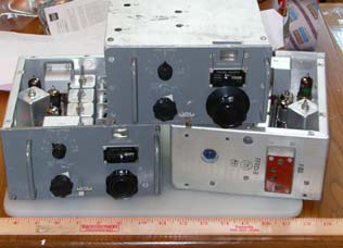
This is a unique receiver, made by the Technical Materiel [sic] Corporation. This was
part of what they called the "Remote Control Receiver System, Model RCR" that was built
for the US Navy. The idea is that the receivers themselves would be in one room, and
a number of remote-control panels would be in a different room. There would be a cable that
went from the control unit through an encoder into a decoder in the receiver room. The control
unit could control three aspects of the receiver (1) Main tuning (+-2000 Hz) (2) BFO frequency, and
(3) RF Gain. The audio gain was controlled on the operator's end.
|
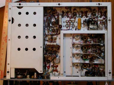
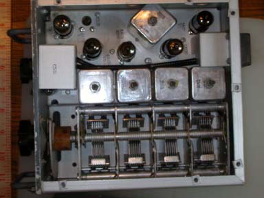
 The band-switching in this receiver is done by removing (!) and replacing the RF drawer. There is
a separate RF drawer for 2-4 MHz, 4-8 MHz, 8-16 MHz and 16-32 MHz. There is also an RF drawer
for 500 kHz (480 to about 520 kHz), which was the international SOS signaling frequency. Ships were
required to monitor that frequency at all times. The "Gibson Girl" SOS rescue radio that was
standard equipment on all Allied bombers (SCR-578) transmitted on 500 kHz.
The band-switching in this receiver is done by removing (!) and replacing the RF drawer. There is
a separate RF drawer for 2-4 MHz, 4-8 MHz, 8-16 MHz and 16-32 MHz. There is also an RF drawer
for 500 kHz (480 to about 520 kHz), which was the international SOS signaling frequency. Ships were
required to monitor that frequency at all times. The "Gibson Girl" SOS rescue radio that was
standard equipment on all Allied bombers (SCR-578) transmitted on 500 kHz.More About the R-5007
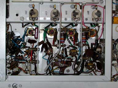
Needless to say, the operator couldn't do any significant tuning of the receiver, since it was
in a different room. I believe most of the time, the receivers used the option crystal control
for fixed frequency operation. I have tried tuning this unit myself - the tuning is very twitchy.
If you sneeze while tuning, you can miss the entire band you are trying to tune. In the units
I have, some previous owner has put 10:1 verniers on two of the tuning drawers. That turns out to
be quite a good idea.
|
Scanned R-5007 Manuals
appropriate manuals. Without schematics and other descriptions, it
is a hopeless task trying to repair these things. I did manage to snag a manual
for the R-5007 and scan it. It has the schematics of all the tuning drawers
as well.