(Click for full-size picture)
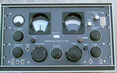
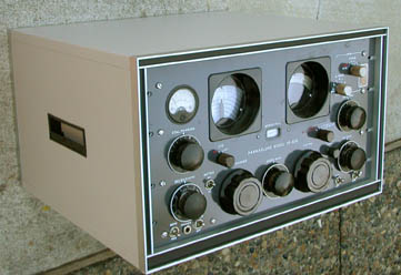
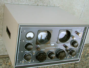
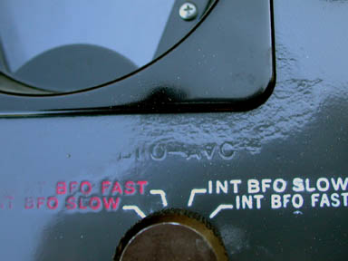
This unit has significant cosmetic problems on the front panel. There was extensive corrosion of the alluminum in the upper-right quadrant of the front panel. I sanded it down as best I could. I did refinish the front panel. I used a darker grey so the engraving and the dials stand out better. I did repaint the some of the knobs on this one. They were quite dull. Note that a number of the knobs are not the original. For instance, the main tuning knobs are General Radio KNS-12 knobs. There are none of the original red knobs. Two were replaced with silver ones, and one with black. I did not try to repaint the meter. I was worried that some paint would get into the mechanism. The markings on the frequency dial were flaking off. I put a dial overlay on it which looks better than new. The vernier dial is the original. Note that in the process of restoration, I completely disassemble the receiver - I take all the gears off on the front panel and remove all the major assemblies (that come off, that is).
I replaced a lot (not all) of the hardware with stanless - especially on the front panel. Every time I took a screw out, I replaced it with stainless, and every time there was a markedly rusty nut or screw that I could get to, I replaced it.
(Click for full-size picture)
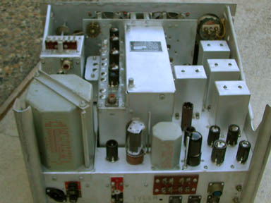
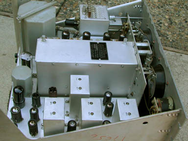
De-Oxit was applied to all the tube sockets. The chassis did not need any work - it was relatively clean and square. It was apparent that this receiver had not been dropped or otherwise mishandled. There were no bent edges or crushed corners. I replaced the missing tube hold-down clip on V17.
All the miniature tubes have the IERC heat-sheding shields or their Cinch equivalents. These are the only tube shields known to actually increase tube life.
(Click for full-size picture)
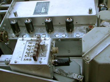
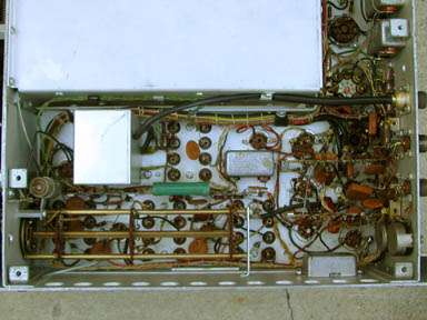
You notice that the FCU (the crystal oscillator) has the 6AH6 tube on this model (as opposed to the 6AC7 on other models). I did check the oscillator output plug on the back, and I did try tuning the receiver by supplying a signal through the connector on the back of the FCU. I had to replace T35. This has been broken and useless on every single JX17 receiver I have ever worked on. I rewind the auto-transformer on a new toroid and seal it in epoxy before installing it. I use a high-frequency material for the toroid that responds easily to 40 MHz and beyond. Although I don't expect anyone to actually try to use the receiver in diversity mode, I did check all the inputs and outputs necessary to make that mode work. I personally feel that the original design is not very good when using the VFO from one receiver to drive the other. The output voltage is not very high, and is even less by the time you get all the way into the slave receiver. It actually works a lot better to drive two receivers from a modern signal generator. That works quite well.
(Click for full-size picture)
(Click for full-size picture)
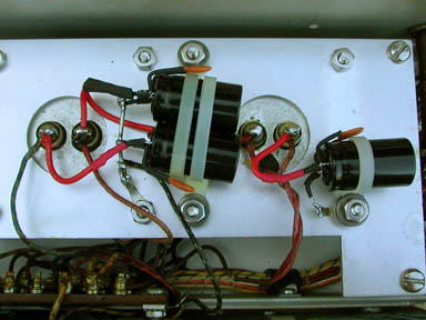
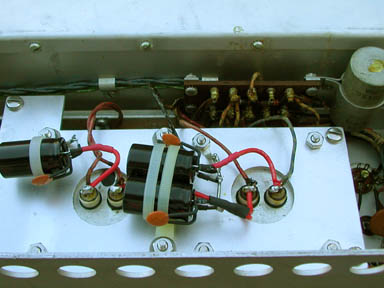
(Click for full-size picture)
(Click for full-size picture)
