SP-600-JX-14, #10546


(Click for full-size picture)

This is an SP-600-JX14, serial number 10546, Signal Corps R-274C/FRR, order no. 3376-Phila-52 (1952, that is).

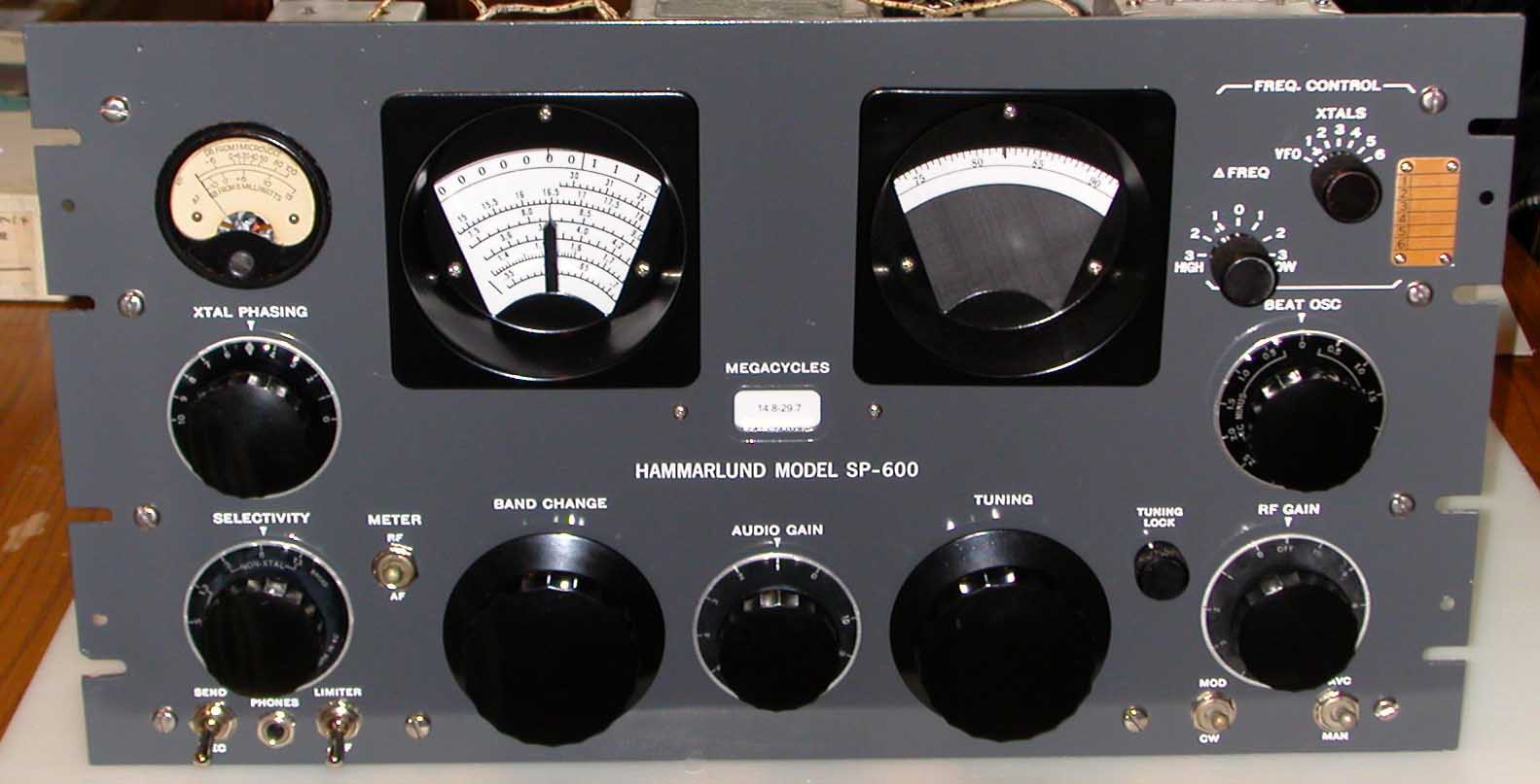
I personally feel that the JX-14 is the best of the SP-600 series (this is a subject of debate, I know). It has a clean AGC system where they don't try to feed the AGC voltage to the second mixer, and the RF stage get the full attenuation of the AGC. I feel this AGC architecture helps keep the IM down in the two RF amplifiers.

I replaced all but a few of the tubes with NOS. I put a 6BZ6 in the 1st RF slot to increase the sensitivity. The tuning dials and the band selector readout were all flaking off. I turned them over (so the originals are still there) and applied dial overlays. I had to replace both the AF and the RF potentiometers - the old ones were scratchy. I also replaced two of the front-panel switches (the ones on the left). One of them was stuck and the other one disintegrated in my hands.

(Click for full-size picture)
I did wash and scrub the sheet metal with a scrubby sponge. No steel wool was used in the process. For the rust stains, I used a stainless-steel bristle brush about the size of a large toothbrush. I replaced the RF connectors for the IF output and antenna input with new silver-plated connectors.

(Click for full-size picture)
This is where I spent most of my time. The RF deck is the heart of the receiver. It has about 30 capacitors inside it. I replaced all of them, plus replaced the odd out-of-spec resistor and a few suspicious-looking wires. Although I don't try to include crystals with the receiver, I did test the FCU to make sure it works properly on all 6 slots. I replaced the RF connector with a new silver-plated one. I actually took this picture right after aligning the receiver, so the hole caps over the alignment access holes were not in place. Also, the capacitor from the FCU was not connected up yet.

(Click for full-size picture)
All the bypass capacitors in the IF and AF sections were replaced with the SBE 716P "orange-drop" capacitors. High frequency sections got ceramic capacitors with 500V ratings. I routinely use 2% silver solder on all joints. I went through and reflowed many of the solder joints (but not all of them). I did test each and every resistor in the unit. A few of the mica capacitors were leaking, and were replaced.

(Click for full-size picture)
This is the rebuilt power section. I replaced the electrolytic with 47-uf, 450-V special high-ripple tolerant, long-life, electrolytics. You should be able to pass this one down to your grand-children.


(Click for full-size picture)

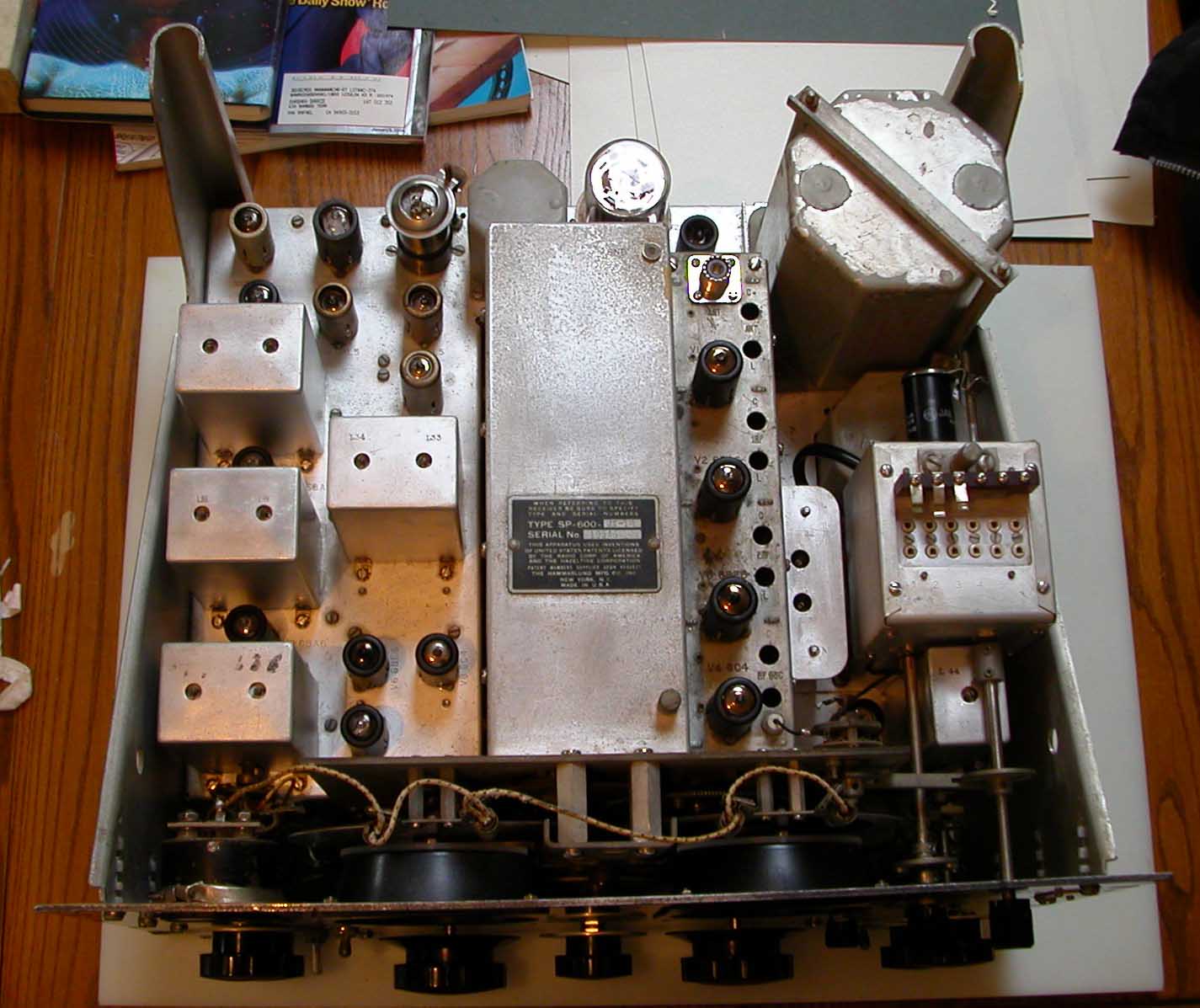
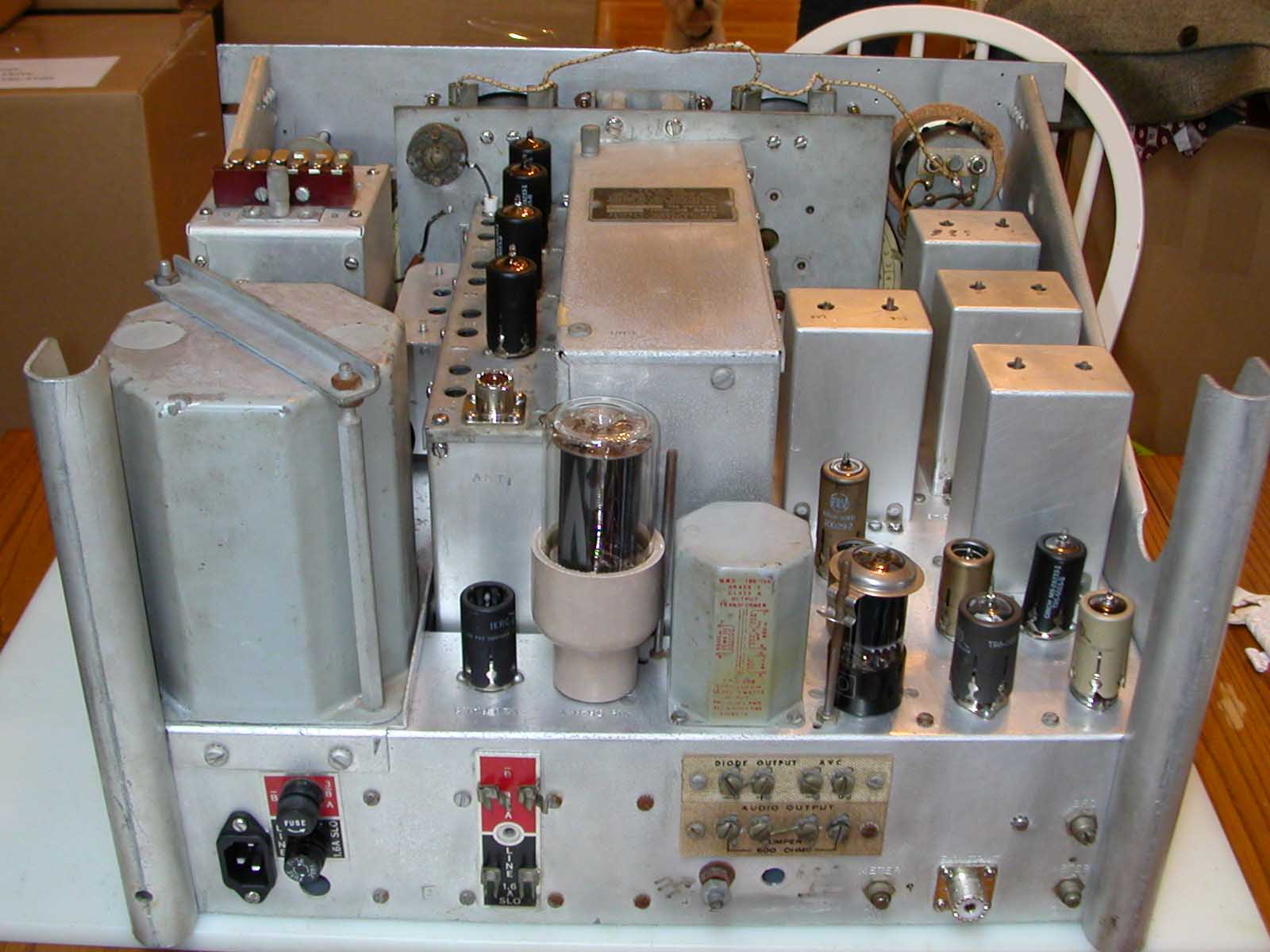
De-Oxit was applied to all the tube sockets. The chassis did not need any major work - it was relatively straight and square. It was apparent that this receiver had not been dropped or otherwise mishandled. There were no bent edges or crushed corners. I replaced the missing tube hold-down clip on V17.

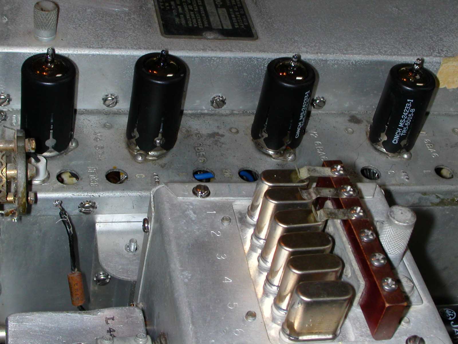
All the miniature tubes have the IERC heat-sheding shields or their Cinch equivalents. These are the only tube shields known to actually increase tube life.