(Click for full-size picture)
|
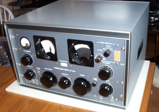
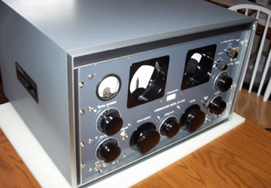
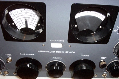
This is an SP-600-JX14, serial number 8447. It has the standard frequency range of 54O khz-54mhz.
It is s Signal Corps. R274C/FRR, order no. 3376-Phila-52. Also designated previously as R-542/FRR.
This model replaces JX-10. It was made in 1952.
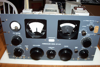
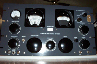
I had to refinish the front panel. It was pretty beat-up with some rust on the bezels.
I used a darker grey so the engraving and the dials stand out better. I don't generally do this, but I did repaint
the knobs on this one. They were quite dull. I did not try to repaint the meter. I
was worried that some paint would get into the mechanism. I did put dial overlays on the
frequency read-out, the vernier, and the band-change indicator (the originals are still there - I
just turned them over and put the dial overlay on the "back" side). I made my own dial overlays
from a more recent receiver.
|
(Click for full-size picture)
|
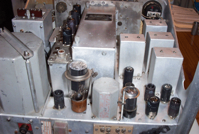
I did wash and scrub the sheet metal, but I did not try to polish it to a mirror shine.
No steel wool was used in the process. De-Oxit was applied to all the tube sockets. The chassis
had been dropped a couple of times (!) and was significantly bent. T2 had been whacked and was
listing to starboard by about 20 degrees. I banged the chassis back flat as well as I could, but
there is still some bowing that is visible. T3 has a significant ding in the top of the can.
The side panels were both replaced from another unit. I replaced the missing tube hold-down clips
on V3, V17, and V19. V19 also needed a new threaded shaft for the hold-down.
|
(Click for full-size picture)
|
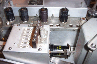
This is where I spent most of my time: the RF deck. All the caps were replaced with 600V
ceramic. A number of resistors were replaced as well. I used a lot of shrink-tubing on the
leads to prevent shorts but still allow you to get a tool in to align it. A number of wires
were replaced. The caps were dressed to hug the ground plane wherever possible.
|
(Click for full-size picture)
|
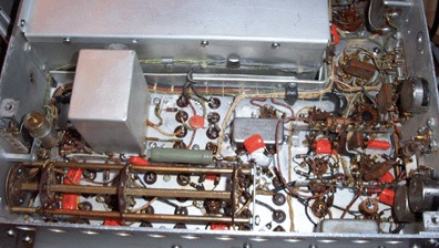
This shows the recapping job on the IF and AF sections. All the orange items are 600V SBE
(née Sprague) "Orange-Drop" 716P capacitors. A number of resistors had to be replaced
in this area as well.
|
(Click for full-size picture)
|
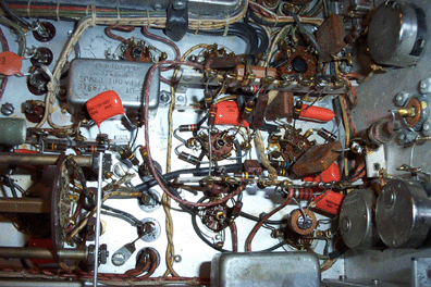
Close-up of the IF and AF sections. A fair amount of hardware was replaced by stainless
in this area.
|
(Click for full-size picture)
|
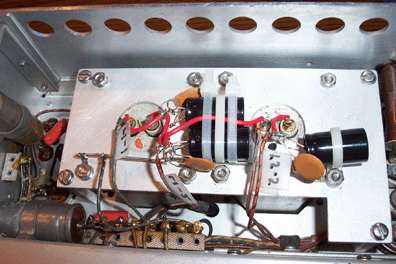
This is the rebuilt power section. I replaced the electrolytic with 47-uf, 450-V special high-ripple
tolerant, long-life, electrolytics. You should be able to pass this one down to your
grand-children.
|
(Click for full-size picture)
|
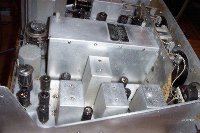
All the miniature tubes have the IERC heat-sheding shields. These are the only tube
shields known to actually increase tube life. You can see the ding in the top of T3 on the lower
right.
|


